While seeking something in DevonThink, I ran across a reference without any source for a lathe spindle stop. I found one, probably not the same. It is a pdf by Robert Sparber. It describes making one for a 12" lathe. It seems both simple and useful. Threaded rod is required. A length of 3/8" threaded rod was located, but is too short. Off to Menards.
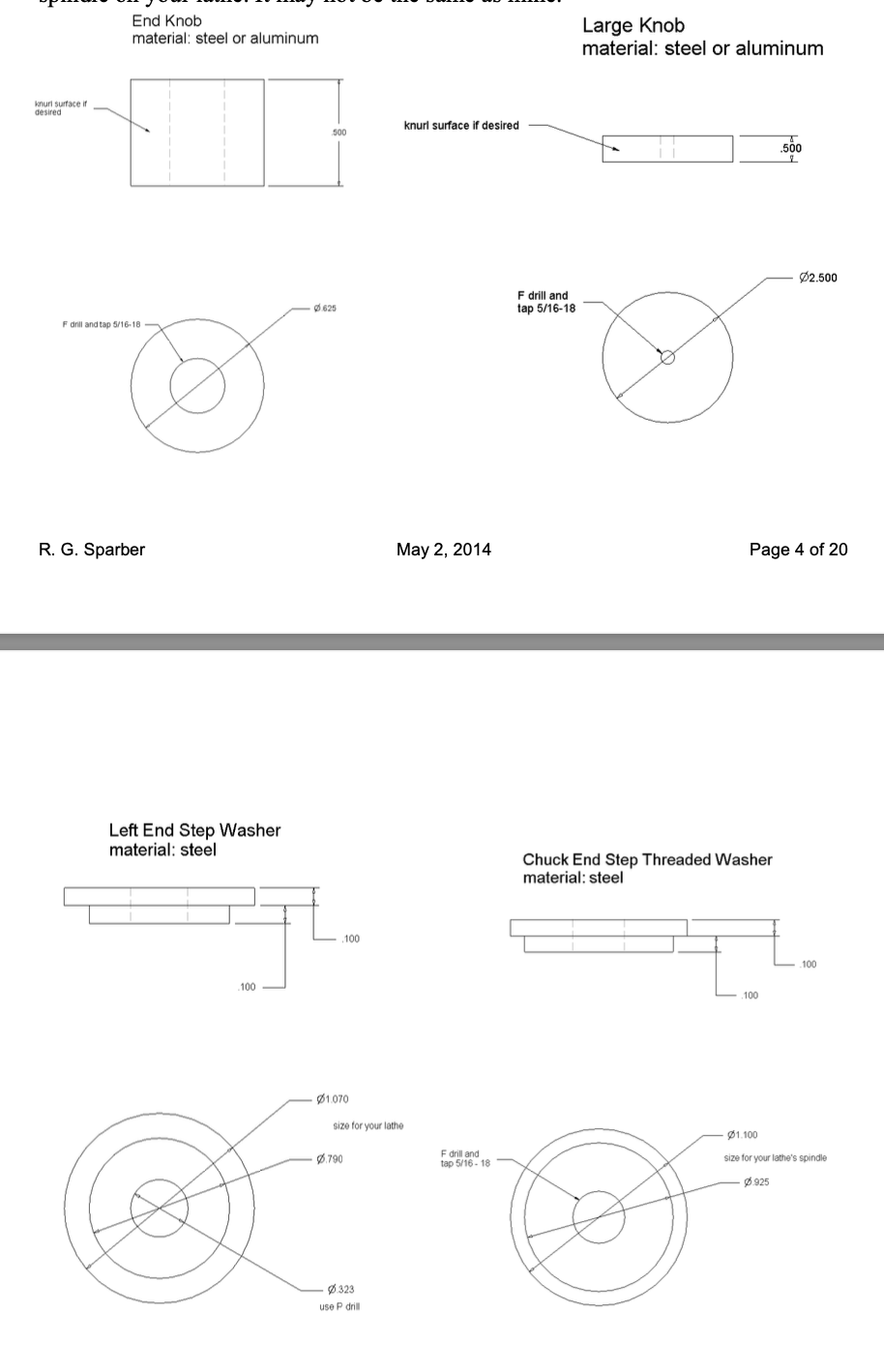
A 2' length of 5/16-18 threaded rod was purchased at Menards. Besides the rod four parts need to be made: two washers for either end of the spindle, one large locknut, and a cap for the end of the rod. I began with the large locknut.
The locknut is a 2 1/2" X 1/2" disk with a threaded hole in the center. I didn't have any aluminum rod that large, but found a rectangle of 1/2" aluminum plate that was 2 1/2" X 3 1/2". This was marked for a hole 1 1/4" in from three sides. The hole was drilled with a center drill, an F drill, and then tapped 5/16-18. 1" was cut off of one side with the bandsaw to give a rough square.
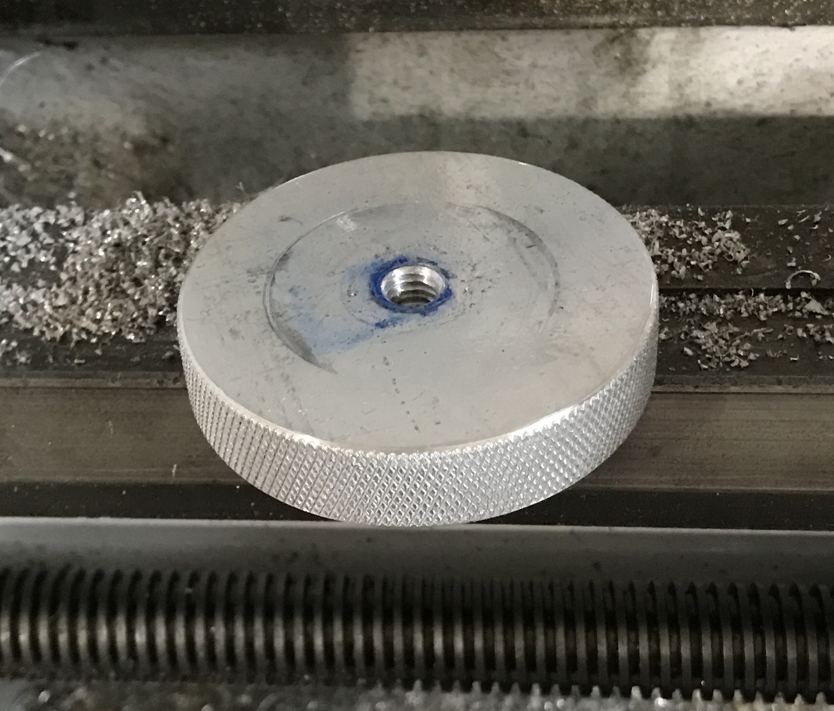
This aluminum square was threaded on the new threaded rod, which was held in a collet in the South Bend lathe. I attempted to turn the square directly into a circle, but gave up after the collet chuck kept popping loose from the spindle due to the intermittent cutting. The corners were then cut off with a hacksaw providing an octagon. There was much less to cut so the 0.010" slow passes were quickly completed. The edges were beveled with a file. The finish was poor, so the side was filed and then sanded with 150 grit paper. The disk was then knurled, using WD-40 as a lubricant. The photo below shows the disk.
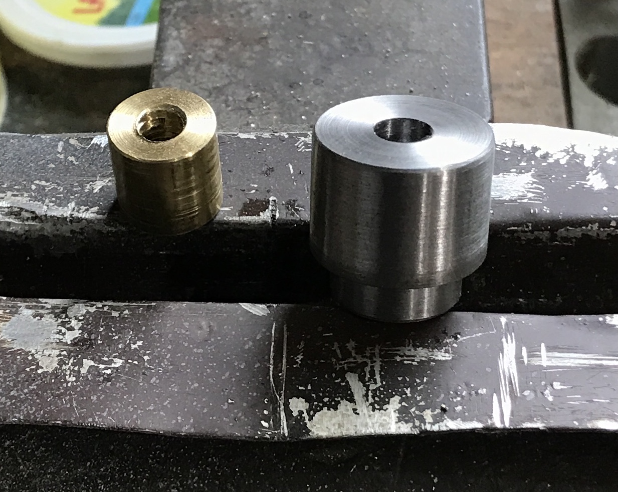
The nut for the end of the rod was made of 5/8" brass round. A 3/4" piece was cut off with a hacksaw. This was faced on both ends in the lathe and drilled through with an F drill. It was tapped 5/16-18. It, like the large locknut, was loose on the threaded rod. It will eventually be glued to the rods end.
The washer for the outside end of the spindle needed to be made significantly thicker than the plan indicates. The spindle ends in a depression in the gear cover, so the washer needs to extend far enough so the large locknut does not contact the cover. A 1" length of 1" steel round was cut with the bandsaw. After facing the end it was reduced to 0.75" for a length of 1/8". It was drilled through with a P drill for clearance on the rod. The opposite end was faced and the outside sanded to remove rust. Both this part and the end nut are shown in the photo below.
The last part to make was the washer for the tailstock end of the spindle. The spec for the spindle at this end is 0.928" ID. A 1/4" length of 1 3/8" round steel was cut off with the bandsaw. It was held in the three jaw chuck and drilled to an F drill and then tapped in the vice. Like the large locknut it was put on the rod and held in the collet with a nut to further lock it in place. The end was faced to the nut. A washer of aluminum was placed behind the workpiece and the steel was reduced to 1.1". Then the diameter was reduced to 0.928" for 0.108". (This width was used as a 7/64" drill was used to set the stop.)
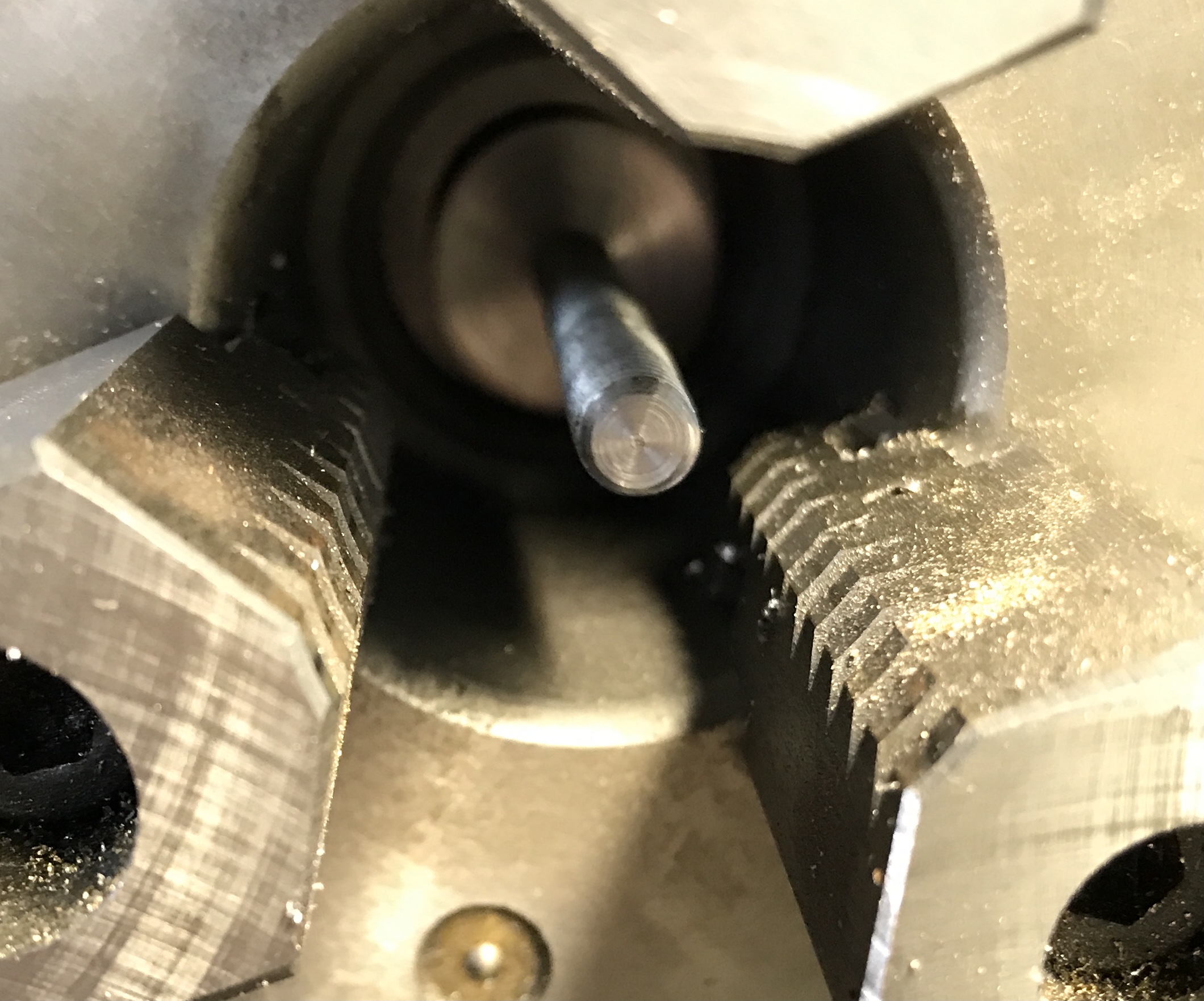
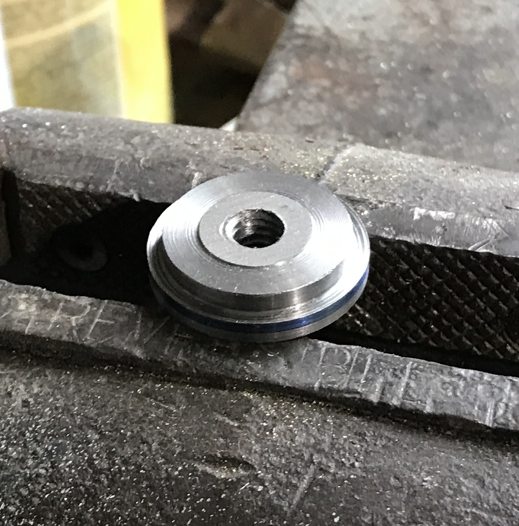
The collet was removed and the washer was checked in the spindle. It did not fit. A measurement with a bore gauge indicated an ID of 0.923". It was too cold to continue this afternoon, so completion of the lathe spindle stop will have to wait until tomorrow. A photo of the washer at this stage is shown below. In addition to fitting the small end to the spindle, the wider end needs to be faced to 0.1".
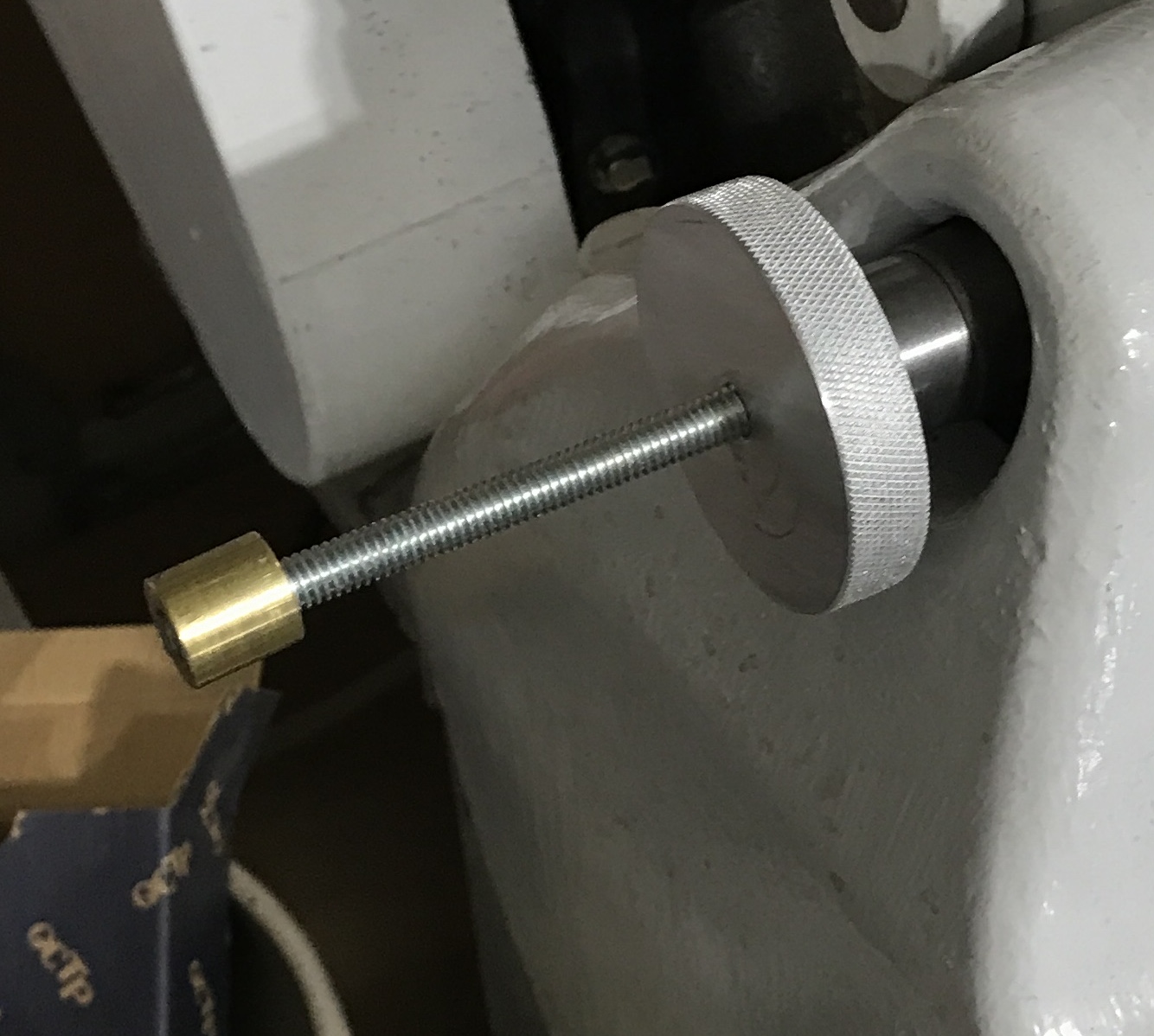
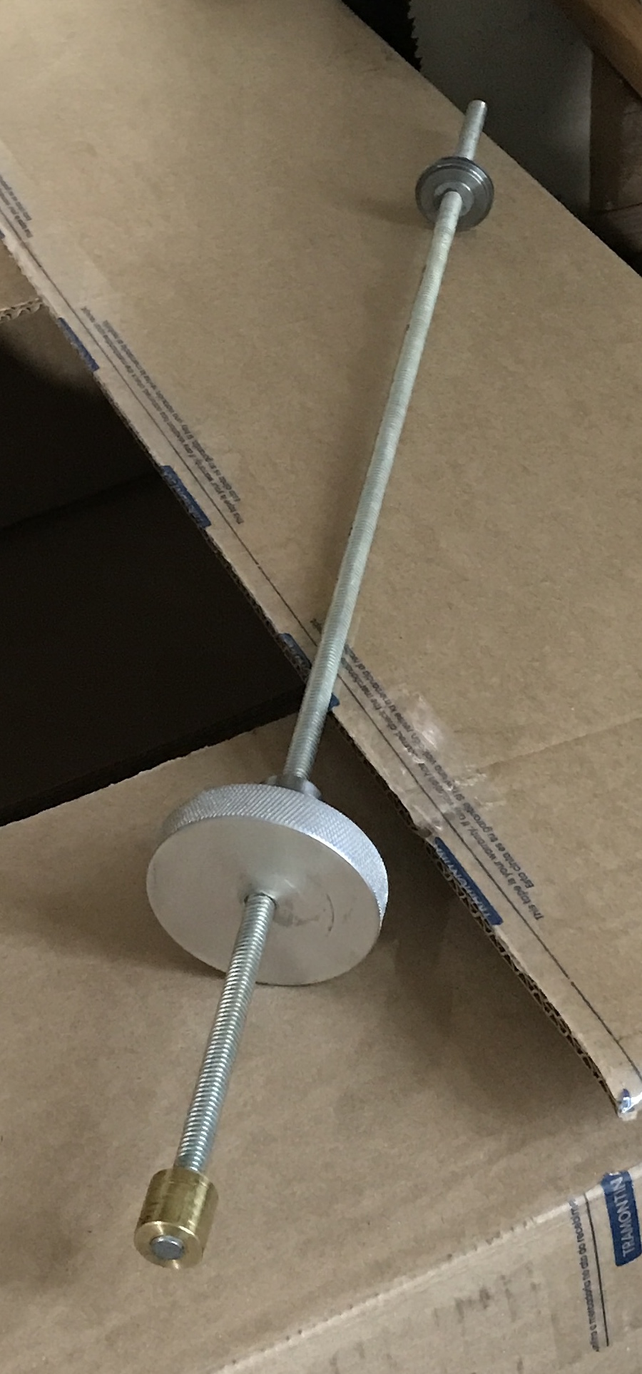
The washer was measured and was 0.939" OD, much larger than expected. It was replaced in the collet and 0.005" (R) was removed. It is now a perfect sliding fit in the spindle. It was turned around in the collet after measuring the width of the wider portion. 0.035" was removed giving the desired width of 0.100". Upon completion of this part the stop was assembled in the spindle. The threaded rod was marked and cut off with a hack saw. The opposite end destined as the stop surface was faced and chamfered. The brass nut was glued to the end using LocTite to complete the lathe spindle stop, which is shown in the photos below.